A transmission line is a device intended to deliver an output signal at a distance from the point of signal input. Transmission lines include power cables, telephone lines, and waveguides. Less obviously perhaps, printed circuit boards, multi-chip modules and even integrated circuit packages have to be considered as transmission lines when operating frequencies are high.
The extra effects which are introduced by transmission line models are: time delay, phase shift, power loss, distortion and reduction of bandwidth.
HSPICE provides facilities for modelling lossless (ideal) and lossy transmission lines.
It also provides facilities to model numerous different physical layouts of the conductors forming the transmission lines. In this document only coaxial cables and twin-lead cables are described. Full details are in the Meta-Software HSPICE manual. See Mr. Wilton if you wish to consult that manual.
This document is also available in PostScript format on the Aston University WWW server. (URL http://www.eeap.aston.ac.uk/eeap/documents/user-guides.html).
The ideal line is modelled as a voltage source and a resistor. The lossy line is modelled as a multiple lumped filter section.

Fig 1. Ideal and lossy transmission line models
Txxx in refin out refout <mname> z0=val td=val L=val
in Signal node (in side)
refin Ground reference for input.
out Signal node (out side)
refout Ground reference for output.
mname U model reference name
z0 Characteristic impedance
td Transmission delay (secs/m)
L Physical length of the transmission line in metres. The default value is 1m.
For 1 wire and ground plane
Uxxx in refin out refout mname L=val
For 2 wires without ground plane (unshielded twin)
Uxxx in1 in2 out1 out2 mname L=val
For 2 wires and ground plane
Uxxx in1 in2 refin out1 out2 refout mname L=val
in, in1, in2 Signal node(s )(in side)
refin Ground reference for input.
out,out1,out2 Signal node(s) (out side)
refout Ground reference for output.
mname U model reference name
L Physical length of the transmission line in metres. The default value is 1m.
The syntax is:
.MODEL mname U LEVEL=3 PLEV=x ELEV=x <DLEV=x>
+ <Pname=val> ...
mname Model name.
PLEV Physical level. Used to distinguish between planar conductors (PLEV=1), Coaxial conductors (PLEV=2),Twin and twisted pair conductors (PLEV=3)
ELEV Electrical level. Used to distinguish modelling via geometry such as thickness, width, dielectric (ELEV=1), pre-calculated equivalent resistance, capacitance and inductance (ELEV=2), measured impedance and delay (ELEV=3).
DLEV Device level. A further level of refinement for different conductor/dielectric configurations.
In this document only geometric and measured parameter modelling are considered.
.MODEL mname U LEVEL=3 PLEV=2 ELEV=1 <Pname=val> ...
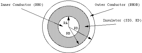
The physical geometry parameters for coaxial cable are shown in Fig. 2 and described in Table 1.

Fig. 2. Coaxial Cable geometry
Name      Unit      Default            Description
RA        m         required           Outer radius of inner conductor
RB        m         required           Inner radius of outer conductor
                                       (shield)
RD        m         RA+RB              Outer radius of outer conductor
                                       (shield)
HGP       m         1.5.RD             Radius to circuit ground point
RHO       [[Omega]  17E-9              Resistivity of conductor material
          ]m                           (default=Copper)
RHOB      [[Omega]  RHO                Resistivity of shield material
          ]m
SIG       [[Omega]  0.0                Conductivity of dielectric
          ]-1m-1
KD                  4.0                Relative dielectric constant
Table
1. Geometric Coaxial cable parameters
Name      Unit      Default            Description
DLEV                0                  Device Level.
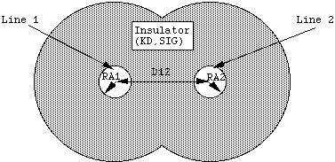
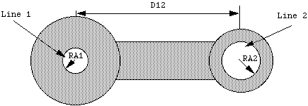
RA1       m         required           Outer radius of conductor 1
RA2       m         RA1                Outer radius of conductor 2
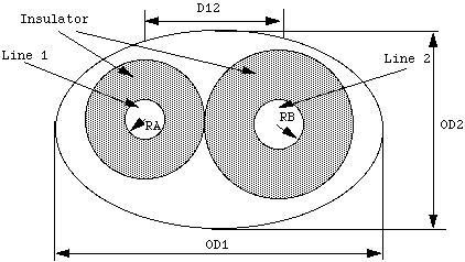
D12       m         required           Distance between conductor centres
RHO       [[Omega]  17E-9              Resistivity of conductor material
          ]m                           (default=Copper)
KD                  4.0                Relative dielectric constant
SIG       [[Omega]  0.0                Conductivity of dielectric
          ]-1m-1
HGP       m         1.5.D12            Radius to circuit ground point
RHOB      [[Omega]  RHO                Resistivity of shield (if present)
          ]m
OD1       m         required           Maximum outer dimension of shield
                                       (if present)
OD2       m         OD1                Minimum outer dimension of shield
                                       (if present)
Table.
2. TwinLead cable parameters

Fig. 3a. TwinLead cable (sea of dielectric) geometry

Fig. 3b. TwinLead cable (insulating spacer) geometry

Fig. 3c. TwinLead cable (with shield) geometry
This modelling method is most useful for standard cable types where the parameters can be extracted from tables.
Name      Unit      Default            Description
ZK        [[Omega]  calculated         Characteristic impedance
          ]
VREL                calculated         Relative velocity of propagation
DELAY     sm-1      calculated         Delay/length
CAPL      Fm-1      1.0                Capacitance/length
AT1       m-1       1.0                Attenuation factor/length
Table 3. Measured parameters
The measured parameters for some standard cables are given below.
+ vrel=0.66 fr1=100meg at1=0.173db
+ vrel=.698 fr1=57meg at1=0.0566db
+ vrel=.733 fr1=100meg at1=0.0458db
WLUMP=val Number of lumps per wavelength for error control. The default value is 20.
MAXL=val Maximum number of lumps per element. The default value is 20.